Porting QMK to a new cheap keyboard
As if I didn’t already have too many half finished projects, I wanted to to try out porting QMK (keyboard firmware) to learn more about QMK and also practice some hardware reverse engineering. This also seemed like a good chance to try out non rubber dome keyboard.
The first thing I did was search for cheapest mechanical keyboards on Amazon. After looking around and making sure it’s not already supported by QMK I chose PERIBOARD-428 . It cost roughly €30.
Initial investigation
After shortly trying it out and observing that typing speed tests were neither better nor worse than with my old keyboard it was time to take it apart.
On one hand I was happy to find that there is no screw hidden under the glued rubber feet. On the other hand it meant that I had removed it for nothing. At least it seemed to stick back well enough keyboard came with a pair of spare. Next candidate for hidden screws were the bigger top feet. Those turned out to be magnetic allowing to be turned 90° for some angle adjustment. What an amazing place to hide screws while keeping the accessible, but no luck again. Last place remaining on the bottom was under the label. Poking it with a screwdriver indicated that there is a round recess in the middle of it, surely a place for screw although it would be slightly weird to have only one screw in the middle of board. But again nothing it was just remains from injection molding process. In the end all the screws were on the top hidden under the keycaps.
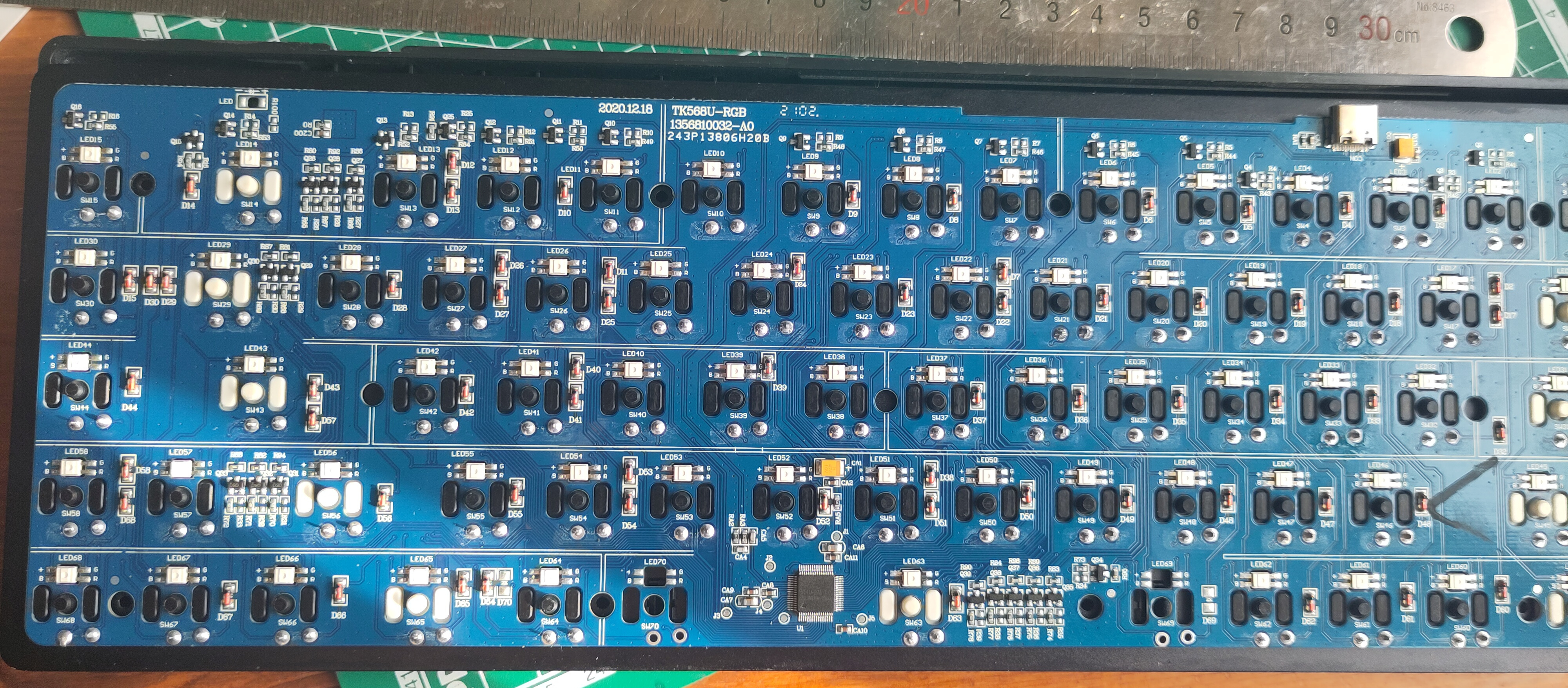
Taking into account functionality there wasn’t too much going on the board. Single diode and RGB led for each switch. Few transistors for driving the LEDs and a single microcontroller. No voltage regulators, no crystal oscillator, no LED driver for all those LEDs.
Searching for the label at the top of PCB “TK568U-RGB” didn’t give any interesting results.
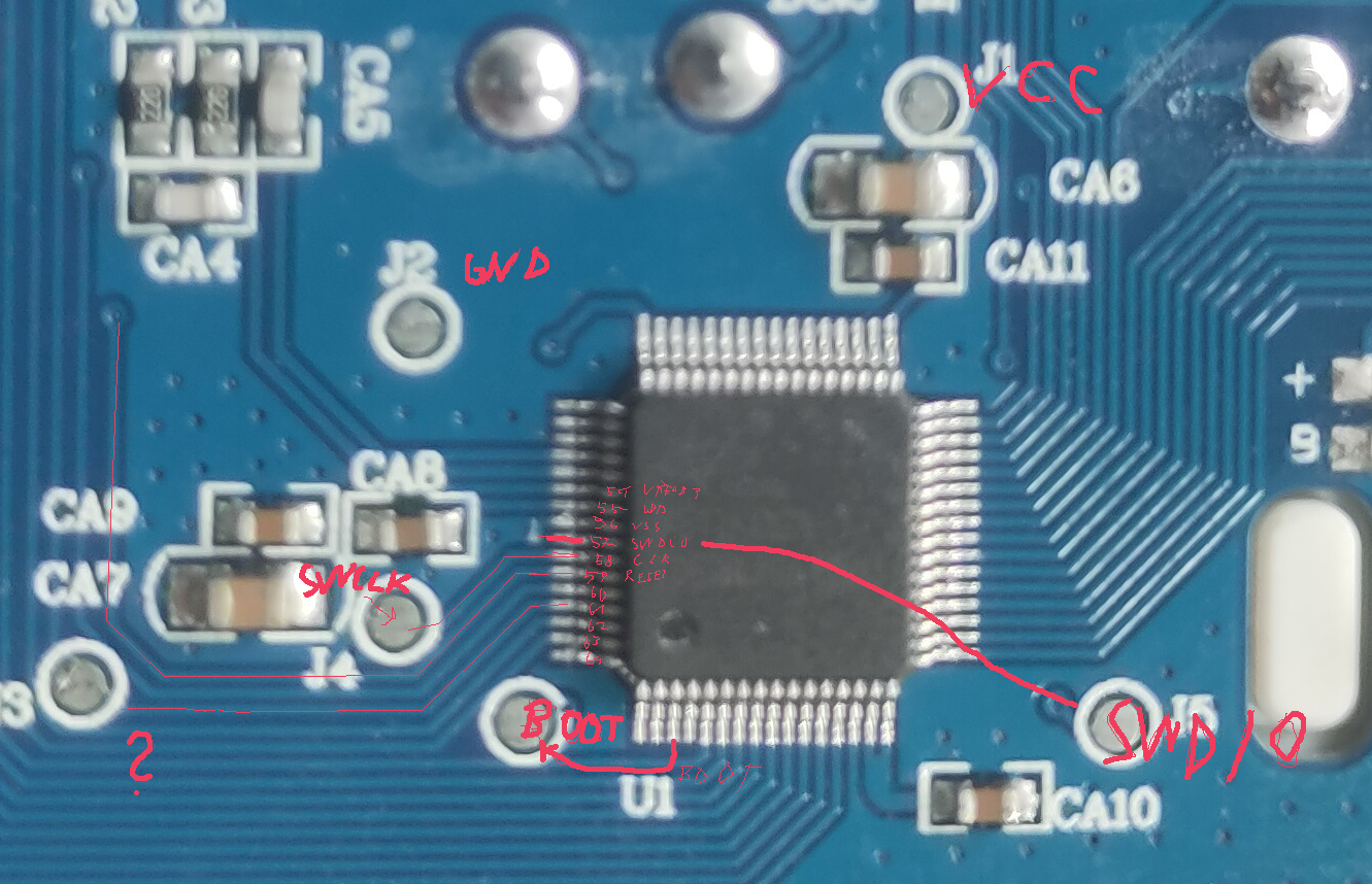
Label on the microcontroller was hard to read and looked like “VSI1K09A” and logo with V in a circle with text that might be “Vision”. First one didn’t give any results. And searching for Vision microcontrollers was mostly filled results about running computer vision on microcontrollers. I also tried search on LCSC with no success. But that didn’t discourage me too much, since it dindn’t feel too confident in digging up information about more obscure eastern electronics manufacturers.
Time to dig in the provided software. Maybe that will give some clues. Extracting files from installer using 7zip and looking for interesting strings in the executables lead me to the website of http://www.eevision.com/ . The logo matched with what was etched on the microcontroller, that’s a good sign. With the help of Google translate I was able to figure out that they are a company specializing in making gaming peripherals for relabeling by other companies. While this confirmed I am on the right track the fact that Vision is a computer peripheral manufacturer and not a microchip manufacturer meant that the microcontroller is probably relabeled by them and getting actual technical information about will be problematic.
After looking around on QMK discord I found that many cheaper keyboards are using SONIX microcontrollers and there is a QMK fork supporting them https://sonixqmk.github.io//SonixDocs/ . Supported MCU list mentioned eVision VS11K09A-1 which is supposedly re-brand of SONIX SN32F248B MCU. Bingo! I had misread VS11 as VSI1 and after starting at the chip carefully it’s probably VS11K09A-1 not VS11K09A. This meant that large portion of the hard work figuring out toolchain and RTOS support for the specific microcontroller is already done. This partially defeats the initial intent, but I wasn’t too keen on dealing with that and before buying keyboard hoped that it will have an MCU from better known manufacturer. I would still have to figure out how the board is wired up, this time that’s enough reverse engineering for me.
Poking around with multimeter indicated the switches are connected more or less in a tidy matrix similar to physical layout similar how it’s done in DIY keyboards. No crazy optimizations like you would see rubber dome keyboards.
LEDs are a slightly different story since there are more than one common way for dealing with them.
Dumping the original firmware
Not strictly necessary and there probably won’t be need to reverse engineering the firmware since the general support for MCU is already figured out, there are no additional ICs on the board and switch and LED connections can be figured out by inspecting the board. But just in case I would still like to dump the firmware and this seem like a good practice with some of the tools.
Like many ARM MCUs it supports SWD interface for reading/writing the program and debugging. https://github.com/SonixQMK/sonix_dumper has more information. First step is identifying the programming pins with the help of datasheets from https://github.com/SonixQMK/Mechanical-Keyboard-Database/tree/main/docs/MCU%20chip and multimeter.
But wait the sonix dumper repository doesn’t actually contain any scripts for dumping it promised to contain. After messing with OpenOCD and less complete instructions I found these instructions https://discord.com/channels/805578807477534750/805578807477534754/849069502272110592 .
There is a script which reuses parts of builtin bootloader ROM for reading the firmware. Not quite sure if reading the flash memory directly failed due to read protection, or it was simply lack of proper configuration. Now that the original firmware is backed up it can be explored further.
One more slightly weird aspect is that for some Sonix MCUs by default trying to read flash memory results in reading of builtin bootloader ROM instead of the firmware data even though from memory map they should be at completely different addresses. To be able to read from the user firmware region it is necessary to switch the register for choosing interrupt vector table. The datasheet doesn’t mention anything that changing it also changes memory map layout. I wonder is it:
- common ARM behavior
- quirk of how boot source/interrupt vector table location change is implemented
- one of the interrupt vector table entries having a special meaning
- interrupts from the bootloader ROM getting executing and doing weird stuff
This can probably be test by configuring the MCU to use the interrupt vector table from RAM. What hap happens if the interrupt table within ram is made to look identical to the one in bootloader ROM? Does whole RAM region gets mapped to address 0x00000000 or does 0x00000000 still point to user firmware in such case?
Analyzing wiring matrix and schematics
First thing to figure out which side has the diode. In my case it was on column side. This meant that analyzing what’s in the same row was quite easy. I could just touch the row side pins for two switches with multimeter to check that they are on the same row. Having a multimeter with continuity mode that beeps when the points touched by probes are connected would have been nice to have, but it was also doable with a cheap multimeter in the resistance mode. You just have to keep looking back and forth between screen and probes, and hope that probes don’t slip while you look away.
One more thing to watch out is any oxide or flux layer on top of contacts. Just lightly touching with the side of probes might not be enough, probe tips are sharp for a reason. Practice on pads you know are connected or opposite side of same pin, to get a feeling how hard you need to stab with the probe tips.
It’s easier to do things in steps. Instead of trying to figure out which switch is connected to which MCU pin, first figure out which switches are connected together in single row, and only then which MCU pin the row is connected to. Same approach will be more important for columns and LED rows because there are multiple components in the path between switch and MCU preventing from directly measuring continuity.
Columns were a bit trickier. Touching pins for two switches would require current to go through two diodes facing opposing directions which doesn’t work. Instead you need to have one probe on the side of diode further away from switch (same as end connected to common column or row) and other probe on the switch. In this case probe direction matters, test first on a single switch+diode which color probe should be on which side. Afterwards go through the switches touching the contact which is on column side. You could have both probes on the ends of diodes, but the switches have bigger contacts easier to touch compared to smd diodes. Also the pairing between switch and corresponding diode isn’t always obvious. As can be seen in the first picture not all diodes are right next to the switch.
For this multimeter should be in diode testing mode you have one. If your multimeter doesn’t have diode mode (like mine) the resistance mode can also be used. The measured number itself will make little sense, but it should be similar number across all diodes of same type. If your multimeter has autorange functionality better disable it, as the reading will depend on the active range so better have it fixed.
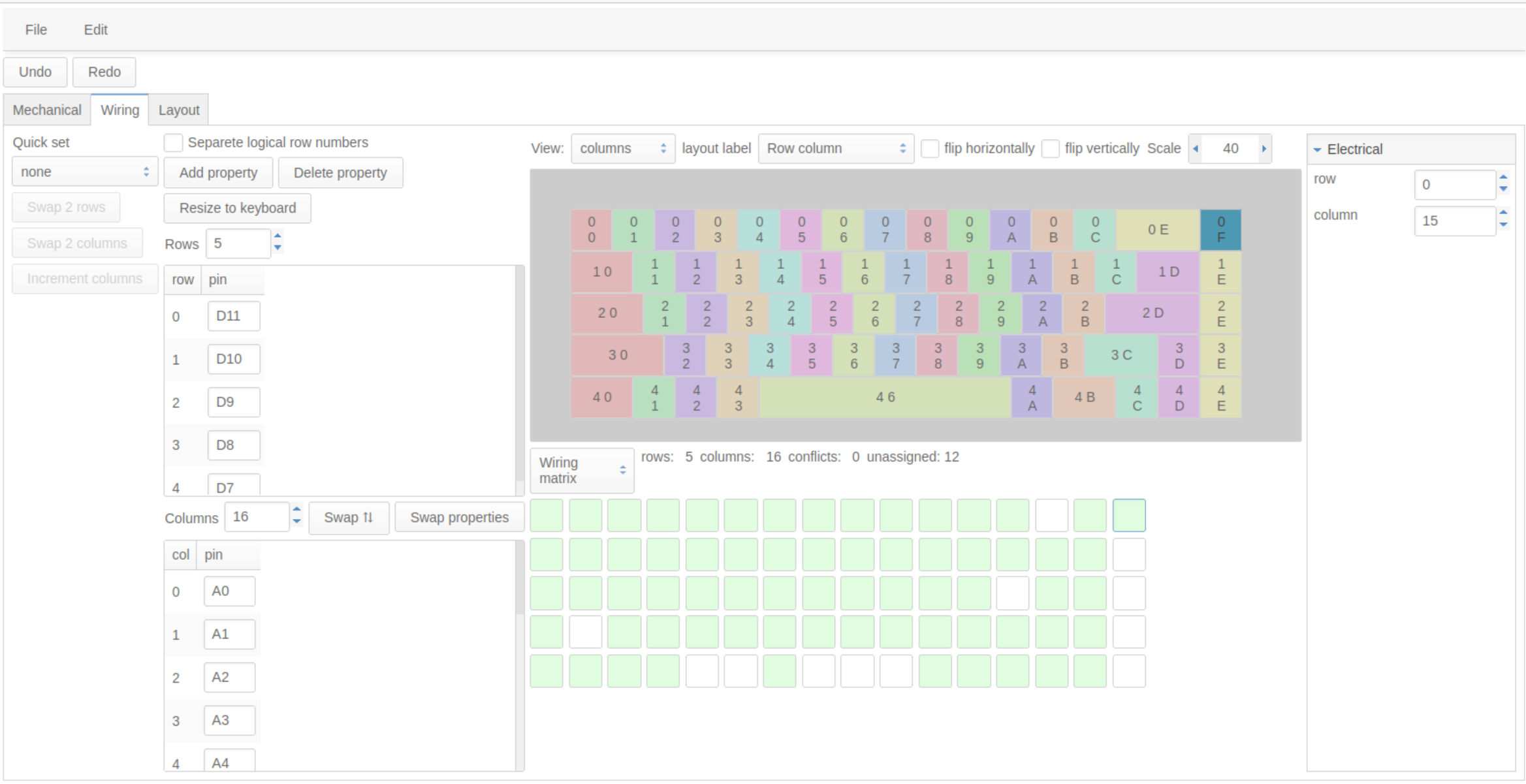
To help keeping track of the rows and columns I used my own kb-editor tool that I had previously started making for other keyboard projects. It helped spotting some of mistakes by highlighting when multiple keys were assigned to same position in matrix. It also later helped avoiding manually creating the most tedious parts of parts of firmware configuration where you have to specify list all keys at least 3-4 times.
The most annoying part was figuring out which pin is connected to a row. The pins are quite small (0.5mm pitch) so unless you are looking straight from top with the probe also held straight it was hard to precisely tell which pin you are touching. Even then I wasn’t fully sure that I am not touching multiple pins. And once I knew which is pin is it, visually counting between 16 identical pins is easy to mess up. I found it easier to do it by feel/sound counting how many pins I drag across.
Some interesting observations: delete key was on a completely separate column with no other switch in the same column even though there are empty spots in previous columns of the same row.
There is an empty spot for led, maybe an illuminated manufacturers logo in different keyboards reusing the same PCB.
I don’t see any obvious current resistors for LEDs. Do those RGB LEDs modules have them builtin, or do they rely on voltage drop and limited current gain of column and row transistors? Now that I am writing this post and looking at the picture, there is one more resistor next to each LED row driver. Maybe those were used for current limiting. But I am too lazy to take apart the keyboard again and verify that.
With all that put together schematics should look something like this, but with a lot more rows and columns. Points labeled as ROW_N, Column_N, LED_ROW_N_C are connected to microcontroller.
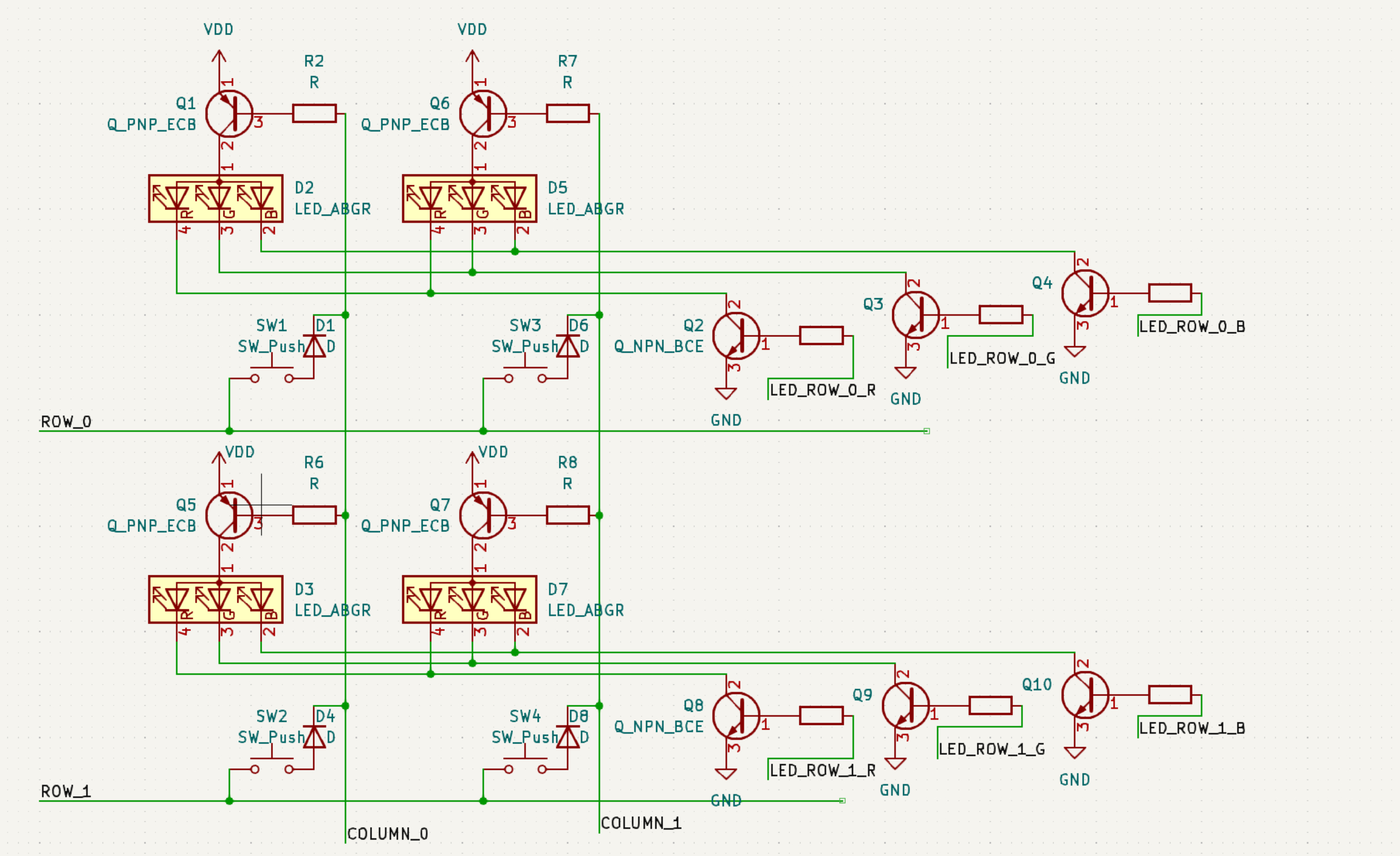
One more important detail was that LED_ROW pins were connected to the MCU pins with hardware PWM support.
Configuring and building firmware
After all the time analyzing wiring matrix it was almost full success on the first try. All the keys worked as intended except space bar.
RGB matrix was little bit trickier. Initially keys were glowing but effects and colors were looking wrong. After having connected logic analyzer to observe what exactly is happening and reading the LED matrix driver code a bit, turned out it was matter of missing appropriate SN32_PWM_OUTPUT_ACTIVE_LEVEL, SN32_RGB_OUTPUT_ACTIVE_LEVEL values.
To anyone creating a QMK config for supporting a new keyboard my recommendations are: use qmk new-keyboard command to generate all the basic config files and documentation templates, start filling out data based on a keyboard using similar MCU and other hardware features. Note that some of the existing keyboards using older style configuration especially if you are looking at some unsupported forks created for support of specific keyboards, the new approach is should allow configuring most things in info.json.
One thing to watch out for complete beginners is that there are at least 4 commonly used .json files: info.json, keymap.json, json file exported by keyboard layout editor, json configuration for VIA. All of those are completely different files with different, format, content and purpose.
- info.json -> used for configuring hardware and features of QMK keyboard
- keymap.json -> used to configure QMK what each key does and multiple layers. More likely to contain user specific stuff. Can be created and edited using QMK configurator.
- keyboard layout editor -> commonly used tool define the visual look of keyboard, there are tools to help generating parts of other configs related to list of keys.
- VIA -> tool for reconfiguring the keymap of QMK keyboards at runtime, without having to rebuild the firmware. Requires VIA specific json file describing the keyboard. Also requires VIA support to be enabled while building QMK firmware. Previously closed source but currently open source.
Rest of the stuff not mentioned bellow are additional bells and whistles. Consult QMK documentation for more information about additional features and configuration.
rules.mk
Using the new configuration approach should be more or less empty.
readme.md
Human readable description of the keyboard. Stick to the template created by QMK tool that way you will have less problems when trying to get the result upstreamed.
info.json
Older QMK versions also had info.json but it contained less information and was used mostly for the online QMK configurator. With more recent QMK versions it’s much more powerful and allows configuring most of the common settings, removing the need to configure things in rules.mk or config.h.
In my case it looked something like this
{
    // this part should be self explainatory
    "manufacturer": "perixx",
    "keyboard_name": "periboard428",
    "maintainer": "karliss", // you, the person adding QMK support for this keyboard, often using github username here
    "bootloader": "sn32-dfu",
    // Bootmagic lite feature https://docs.qmk.fm/#/feature_bootmagic
    // Used to enter bootloader by holding a key while plugging in the keyboard.
    // With my keyboard and probably most other Sonix keyboards didn't work out of the box due to the way shared key, RGB matrix scanning works.
    // Was able to get it working by writing little bit of C code to deal with it.
    "bootmagic": {
        "enabled": true,
        "matrix": [0, 15] // by default [0, 0]/esc key, no need to set it unless you have an unusual matrix
        // Set it DEL instead of default [0, 0] since it was on separate column/row and the secondary label (R). Maybe that's why the original keyboard authors placed it in a separate column.
        // Although the code would probably also with work with rest of keys.
    },
    // Depends on which direction the per switch diode is connected. Affects whether order in which key matrix is scanned.
    "diode_direction": "ROW2COL",
    // Configuration of EEPROM or other storage for saving persistent settings
    // Some MCUs have builtin EEPROM memory, some keyboards have external EEPROM chip
    // In this case there was none so I have to use the leftover space from flash memory used for storing the program.
    "eeprom": {
        "driver": "wear_leveling",
        "wear_leveling": {
            "backing_size": 2048,
            "driver": "sn32_flash"
        }
    },
    // some common QMK features
    "features": {
        "command": true,
        "console": false,
        "extrakey": true,
        "mousekey": true,
        "nkro": true,
        "rgb_matrix": true
    },
    // the pins connected to switch matrix
    // SN32F240 documentation calls the pins P0.0, P0.1, P1.0 instead of A0, A1, B0. That's why it's useful to take a look at configurations for keyboards using similar MCU to figure out which naming pattern is used.
    "matrix_pins": {
        "cols": ["A0", "A1", "A2", "A3", "A4", "A5", "A6", "A7", "A8", "A9", "A10", "A11", "A12", "A13", "A14", "B0"],
        "rows": ["D11", "D10", "D9", "D8", "D7"]
    },
    // again worth looking keyboards using similar MCU, since the exact name used by build scripts and header files might slightly differ from the name used in MCU datasheet. Sometimes there might few variations of the same chip with some of letters referring to details like physical package type (QFP, QFN, DIP) which are not important from the code perspective, so the code might refer to the same family using common name dropping some of last letters or replacing some in the middle with placeholder
    // In case of Sonix based keyboards things are a bit more complicated since those chips in many keyboards are re-branded as eVision or HFD with completely different part numbers.
    // There is a table in https://sonixqmk.github.io//SonixDocs/ for converting between matching versions.
    "processor": "SN32F248BF",
    // config for rgb LED matrix
    "rgb_matrix": {
        // which animation effects to include in firmware, more effects take more space
        "animations": {
            "band_val": true,
            "breathing": true,
            "cycle_left_right": true,
            "cycle_pinwheel": true,
            "cycle_spiral": true,
            "digital_rain": true,
            "gradient_left_right": true,
            "gradient_up_down": true,
            "raindrops": true,
            "solid_reactive_cross": true,
            "solid_reactive_simple": true,
            "splash": true,
            "typing_heatmap": true
        },
        // the driver for shared key/RGB matrix using the sonix hardware PWM
        // but there are also some sonix keyboards using external LED matrix controller chip
        "driver": "sn32f24xb",
        // LED matrix description
        "layout": [
            {"matrix": [0, 0], "x": 0, "y": 0, "flags": 4},
            {"matrix": [0, 1], "x": 15, "y": 0, "flags": 4},
            {"matrix": [0, 2], "x": 30, "y": 0, "flags": 4},
            {"matrix": [0, 3], "x": 45, "y": 0, "flags": 4},
            {"matrix": [0, 4], "x": 60, "y": 0, "flags": 4},
            {"matrix": [0, 5], "x": 75, "y": 0, "flags": 4},
            {"matrix": [0, 6], "x": 90, "y": 0, "flags": 4},
            {"matrix": [0, 7], "x": 105, "y": 0, "flags": 4},
            {"matrix": [0, 8], "x": 119, "y": 0, "flags": 4},
            {"matrix": [0, 9], "x": 134, "y": 0, "flags": 4},
            {"matrix": [0, 10], "x": 149, "y": 0, "flags": 4},
            {"matrix": [0, 11], "x": 164, "y": 0, "flags": 4},
            {"matrix": [0, 12], "x": 179, "y": 0, "flags": 4},
            {"matrix": [0, 14], "x": 202, "y": 0, "flags": 4},
            {"matrix": [0, 15], "x": 224, "y": 0, "flags": 4},
            {"matrix": [1, 0], "x": 4, "y": 16, "flags": 4},
            {"matrix": [1, 1], "x": 22, "y": 16, "flags": 4},
            {"matrix": [1, 2], "x": 37, "y": 16, "flags": 4},
            {"matrix": [1, 3], "x": 52, "y": 16, "flags": 4},
            {"matrix": [1, 4], "x": 67, "y": 16, "flags": 4},
            {"matrix": [1, 5], "x": 82, "y": 16, "flags": 4},
            {"matrix": [1, 6], "x": 97, "y": 16, "flags": 4},
            {"matrix": [1, 7], "x": 112, "y": 16, "flags": 4},
            {"matrix": [1, 8], "x": 127, "y": 16, "flags": 4},
            {"matrix": [1, 9], "x": 142, "y": 16, "flags": 4},
            {"matrix": [1, 10], "x": 157, "y": 16, "flags": 4},
            {"matrix": [1, 11], "x": 172, "y": 16, "flags": 4},
            {"matrix": [1, 12], "x": 187, "y": 16, "flags": 4},
            {"matrix": [1, 13], "x": 205, "y": 16, "flags": 4},
            {"matrix": [1, 14], "x": 224, "y": 16, "flags": 4},
            {"matrix": [2, 0], "x": 6, "y": 32, "flags": 4},
            {"matrix": [2, 1], "x": 26, "y": 32, "flags": 4},
            {"matrix": [2, 2], "x": 41, "y": 32, "flags": 4},
            {"matrix": [2, 3], "x": 56, "y": 32, "flags": 4},
            {"matrix": [2, 4], "x": 71, "y": 32, "flags": 4},
            {"matrix": [2, 5], "x": 86, "y": 32, "flags": 4},
            {"matrix": [2, 6], "x": 101, "y": 32, "flags": 4},
            {"matrix": [2, 7], "x": 116, "y": 32, "flags": 4},
            {"matrix": [2, 8], "x": 131, "y": 32, "flags": 4},
            {"matrix": [2, 9], "x": 146, "y": 32, "flags": 4},
            {"matrix": [2, 10], "x": 161, "y": 32, "flags": 4},
            {"matrix": [2, 11], "x": 175, "y": 32, "flags": 4},
            {"matrix": [2, 13], "x": 200, "y": 32, "flags": 4},
            {"matrix": [2, 14], "x": 224, "y": 32, "flags": 4},
            {"matrix": [3, 0], "x": 9, "y": 48, "flags": 4},
            {"matrix": [3, 2], "x": 34, "y": 48, "flags": 4},
            {"matrix": [3, 3], "x": 49, "y": 48, "flags": 4},
            {"matrix": [3, 4], "x": 63, "y": 48, "flags": 4},
            {"matrix": [3, 5], "x": 78, "y": 48, "flags": 4},
            {"matrix": [3, 6], "x": 93, "y": 48, "flags": 4},
            {"matrix": [3, 7], "x": 108, "y": 48, "flags": 4},
            {"matrix": [3, 8], "x": 123, "y": 48, "flags": 4},
            {"matrix": [3, 9], "x": 138, "y": 48, "flags": 4},
            {"matrix": [3, 10], "x": 153, "y": 48, "flags": 4},
            {"matrix": [3, 11], "x": 168, "y": 48, "flags": 4},
            {"matrix": [3, 12], "x": 189, "y": 48, "flags": 4},
            {"matrix": [3, 13], "x": 209, "y": 48, "flags": 4},
            {"matrix": [3, 14], "x": 224, "y": 48, "flags": 4},
            {"matrix": [4, 0], "x": 4, "y": 64, "flags": 4},
            {"matrix": [4, 1], "x": 22, "y": 64, "flags": 4},
            {"matrix": [4, 2], "x": 37, "y": 64, "flags": 4},
            {"matrix": [4, 3], "x": 52, "y": 64, "flags": 4},
            {"matrix": [4, 6], "x": 105, "y": 64, "flags": 4},
            {"matrix": [4, 10], "x": 157, "y": 64, "flags": 4},
            {"matrix": [4, 11], "x": 175, "y": 64, "flags": 4},
            {"matrix": [4, 12], "x": 194, "y": 64, "flags": 4},
            {"matrix": [4, 13], "x": 209, "y": 64, "flags": 4},
            {"matrix": [4, 14], "x": 224, "y": 64, "flags": 4}
        ]
    },
    "url": "https://perixx.com/products/mechanical-usb-gaming-65-keyboard-customizable-rgb-backlit-n-key-rollover-anti-ghosting",
    // USB PID/VID a bit of mess with hobby projects. All commercial products should obtain unique PID/VID from USB-IF.
    // There are ways to get a free PID more suitable for open source projects,
    // but if it's a personal one off project and works with standard USB hid drivers it's  not wort the effort and somewhat wasteful.
    // Many noncomercial QMK keyboards just choose a random number (preferably checking if it doesn't conflict with existing stuff).
    "usb": {
        "device_version": "0.0.1",
        "pid": "0xB428",
        "vid": "0xFEED"
    },
    // Layout defines the physical key positions, and their mapping
    // to scanning matrix.
    // One keyboard could have multiple layouts if the same board get's reused
    // for ANSI, ISO or regional keyboard variations.
    "layouts": {
        "LAYOUT": {
            "layout": [
                {"label": "ESC", "matrix": [0, 0], "x": 0, "y": 0},
                {"label": "1", "matrix": [0, 1], "x": 1, "y": 0},
                {"label": "2", "matrix": [0, 2], "x": 2, "y": 0},
                {"label": "3", "matrix": [0, 3], "x": 3, "y": 0},
                {"label": "4", "matrix": [0, 4], "x": 4, "y": 0},
                {"label": "5", "matrix": [0, 5], "x": 5, "y": 0},
                {"label": "6", "matrix": [0, 6], "x": 6, "y": 0},
                {"label": "7", "matrix": [0, 7], "x": 7, "y": 0},
                {"label": "8", "matrix": [0, 8], "x": 8, "y": 0},
                {"label": "9", "matrix": [0, 9], "x": 9, "y": 0},
                {"label": "0", "matrix": [0, 10], "x": 10, "y": 0},
                {"label": "-", "matrix": [0, 11], "x": 11, "y": 0},
                {"label": "=", "matrix": [0, 12], "x": 12, "y": 0},
                {"label": "Backspace", "matrix": [0, 14], "x": 13, "y": 0, "w": 2},
                {"label": "Del", "matrix": [0, 15], "x": 15, "y": 0},
                {"label": "Tab", "matrix": [1, 0], "x": 0, "y": 1, "w": 1.5},
                {"label": "q", "matrix": [1, 1], "x": 1.5, "y": 1},
                {"label": "w", "matrix": [1, 2], "x": 2.5, "y": 1},
                {"label": "e", "matrix": [1, 3], "x": 3.5, "y": 1},
                {"label": "r", "matrix": [1, 4], "x": 4.5, "y": 1},
                {"label": "t", "matrix": [1, 5], "x": 5.5, "y": 1},
                {"label": "y", "matrix": [1, 6], "x": 6.5, "y": 1},
                {"label": "u", "matrix": [1, 7], "x": 7.5, "y": 1},
                {"label": "i", "matrix": [1, 8], "x": 8.5, "y": 1},
                {"label": "o", "matrix": [1, 9], "x": 9.5, "y": 1},
                {"label": "p", "matrix": [1, 10], "x": 10.5, "y": 1},
                {"label": "[", "matrix": [1, 11], "x": 11.5, "y": 1},
                {"label": "]", "matrix": [1, 12], "x": 12.5, "y": 1},
                {"label": "\\", "matrix": [1, 13], "x": 13.5, "y": 1, "w": 1.5},
                {"label": "Ins", "matrix": [1, 14], "x": 15, "y": 1},
                {"label": "Caps Lock", "matrix": [2, 0], "x": 0, "y": 2, "w": 1.75},
                {"label": "a", "matrix": [2, 1], "x": 1.75, "y": 2},
                {"label": "s", "matrix": [2, 2], "x": 2.75, "y": 2},
                {"label": "d", "matrix": [2, 3], "x": 3.75, "y": 2},
                {"label": "f", "matrix": [2, 4], "x": 4.75, "y": 2},
                {"label": "g", "matrix": [2, 5], "x": 5.75, "y": 2},
                {"label": "h", "matrix": [2, 6], "x": 6.75, "y": 2},
                {"label": "j", "matrix": [2, 7], "x": 7.75, "y": 2},
                {"label": "k", "matrix": [2, 8], "x": 8.75, "y": 2},
                {"label": "l", "matrix": [2, 9], "x": 9.75, "y": 2},
                {"label": ";", "matrix": [2, 10], "x": 10.75, "y": 2},
                {"label": "'", "matrix": [2, 11], "x": 11.75, "y": 2},
                {"label": "Enter", "matrix": [2, 13], "x": 12.75, "y": 2, "w": 2.25},
                {"label": "PgUp", "matrix": [2, 14], "x": 15, "y": 2},
                {"label": "Shift", "matrix": [3, 0], "x": 0, "y": 3, "w": 2.25},
                {"label": "z", "matrix": [3, 2], "x": 2.25, "y": 3},
                {"label": "x", "matrix": [3, 3], "x": 3.25, "y": 3},
                {"label": "c", "matrix": [3, 4], "x": 4.25, "y": 3},
                {"label": "v", "matrix": [3, 5], "x": 5.25, "y": 3},
                {"label": "b", "matrix": [3, 6], "x": 6.25, "y": 3},
                {"label": "n", "matrix": [3, 7], "x": 7.25, "y": 3},
                {"label": "m", "matrix": [3, 8], "x": 8.25, "y": 3},
                {"label": ",", "matrix": [3, 9], "x": 9.25, "y": 3},
                {"label": ".", "matrix": [3, 10], "x": 10.25, "y": 3},
                {"label": "/", "matrix": [3, 11], "x": 11.25, "y": 3},
                {"label": "Shift", "matrix": [3, 12], "x": 12.25, "y": 3, "w": 1.75},
                {"label": "Up", "matrix": [3, 13], "x": 14, "y": 3},
                {"label": "PgDn", "matrix": [3, 14], "x": 15, "y": 3},
                {"label": "Ctrl", "matrix": [4, 0], "x": 0, "y": 4, "w": 1.5},
                {"label": "Win", "matrix": [4, 1], "x": 1.5, "y": 4},
                {"label": "Alt", "matrix": [4, 2], "x": 2.5, "y": 4},
                {"label": "Fn", "matrix": [4, 3], "x": 3.5, "y": 4},
                {"matrix": [4, 6], "x": 4.5, "y": 4, "w": 6},
                {"label": "AltGr", "matrix": [4, 10], "x": 10.5, "y": 4},
                {"label": "Ctrl", "matrix": [4, 11], "x": 11.5, "y": 4, "w": 1.5},
                {"label": "Left", "matrix": [4, 12], "x": 13, "y": 4},
                {"label": "Down", "matrix": [4, 13], "x": 14, "y": 4},
                {"label": "Right", "matrix": [4, 14], "x": 15, "y": 4}
            ]
        }
    }
}
config.h
If sonix keyboards were fully supported by upstream QMK this file could potentially also be empty/not included. But currently few settings can’t be configured in info.json.
#define RGB_MATRIX_LED_COUNT 68
// sn32f24xb LED driver specific config, corresponds to pins connected to PWM pins connected to row drivers
#define SN32_RGB_MATRIX_ROW_PINS \
    { C4, C6, C5, C7, C9, C8, C10, C12, C11, B6, B8, B7, B9, B11, B10 }


// Following config will depend how exactly everything is wired up in the specific keyboard. Not all the Sonix keyboards are the same. There are 2 (maybe 4) reasonable combinations it could be done.
// Since key columns are also shared with PNP transistors controlling LED columns, unselected columns need to be driven high.
#define MATRIX_UNSELECT_DRIVE_HIGH
// there
// the column driving PNP transistors are activated by setting the pins low
#define SN32_RGB_OUTPUT_ACTIVE_LEVEL SN32_RGB_OUTPUT_ACTIVE_LOW
// row NPN transistors connected to PWM output pins are activated by low signal
#define SN32_PWM_OUTPUT_ACTIVE_LEVEL SN32_PWM_OUTPUT_ACTIVE_HIGH
keymaps/name/keymap.json
Last but not the least important part is keymap.json which defines what should happen when you press a key. That also includes stuff like FN+Key doing something special. More advanced configuration might contain even more layers.
Older QMK version defined this in a C file. But just like with keyboard config it can now be defined using a json file. Which has the benefits of being more easy to generate or read and edit by various tools compared to free from c file.
When I was making it I made it by hand. But it seems like latest version of QMK configurator now supports importing a custom info.json file and creating keymap.json for it. Older versions supported importing info.json for testing purpose, but didn’t support editing and downloading keymap. Previously that only worked only for keyboards which included in upstream QMK.
The process should be:
- import info.json using
Ctrl+Shift+I(this is somewhat hidden option since people are encouraged to upstream their keyboard support) - define what each key should do in each layer
- download the keymap.json and place it in corresponding keymap folder
For the keyboards that have upstream support you can not only download the keymap.json, but also compile and download the full firmware.